|
Model
|
Volume
(m³)
|
Impeller diameter(mm)
|
Productsive
Capacity (t/h)
(m³/min)
|
Impeller speed
(r/min)
|
Drive motor
|
Scraper motor
|
Internal size
(L×W×H) (mm)
|
Weight
(kg)
|
|
Model
|
Power
(kw)
|
Model
|
Power
(kw)
|
|
XJK-0.13
|
0.13
|
200
|
0.05~0.16
|
593
|
Y90L-4
|
1.5
|
Y80M2-4
|
0.75
|
504×520×700
|
266
|
|
XJK-0.23
|
0.23
|
250
|
0.12~0.28
|
504
|
Y100L2-4
|
3.0
|
Y80M2-4
|
0.75
|
604×620×820
|
389
|
|
XJK-0.35
|
0.35
|
300
|
0.15~0.5
|
500
|
Y90L-4
|
1.5
|
Y80M2-4
|
0.75
|
700×700×906
|
430
|
|
XJK-0.62
|
0.62
|
350
|
0.3~0.9
|
400
|
Y132S-6
|
3.0
|
Y90L-6
|
1.1
|
820×900×1156
|
630
|
|
XJK-1.1
|
1.1
|
500
|
0.6~1.6
|
330
|
Y132M2-6
|
5.5
|
Y90L-6
|
1.1
|
1100×1100×1269
|
1300
|
|
XJK-2.8
|
2.8
|
600
|
1.5~3.5
|
280
|
Y160L-6
|
11.0
|
Y100L-6
|
1.5
|
1750×1600×1450
|
2325
|
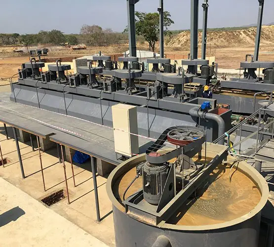
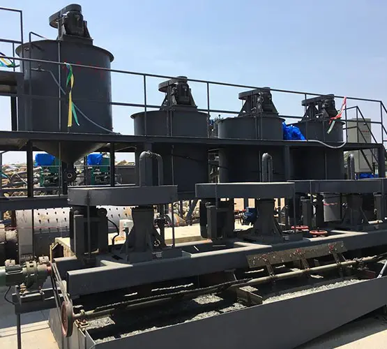
Figure XJ Flotation Machine Structure
1—shaft; 2—impeller; 3—cover plate; 4—connecting pipe; 5—sand hole gate screw;
6—intake pipe; 7—pipe gas pipe; 8—seat plate; 9-Bearing; 10 - pulley;
11 - overflow gate hand wheel and screw; 12 - scraper; 13 - foam overflow lip; 14 - trough; 15 - sand gate;
16—feed pipe (suction pipe); 17—overflow raft; 18—overflow gate; 19—sluice shell (intermediate outdoor wall);
20—sand hole 21-sand Hole gate; 22 - medium mine return hole; 23 - DC tank front overflow weir; 24 - motor and pulley; 25 - circulation hole adjustment
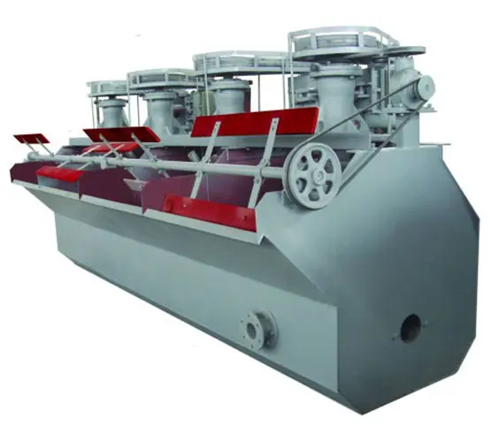
The basic structure of the XJ flotation machine is shown in the figure. It consists of two flotation tanks. The first tank (with the feed pipe) is the suction tank and the second tank is the DC tank. There is a gap between the two tanks. Intermediate room. The impeller is mounted at the lower end of the main shaft, and the upper end of the main shaft has a pulley that is rotated by a motor. Air is drawn in by the intake pipe. The level of slurry in each set of flotation cells is adjusted by the gate. A cover plate and an air cylinder (also called a standpipe) are mounted above the impeller. The air cylinder is provided with a hole for installation into the slurry pipe, the intermediate mine return pipe or as a slurry circulation, and the size of the hole can be adjusted by the tie rod.
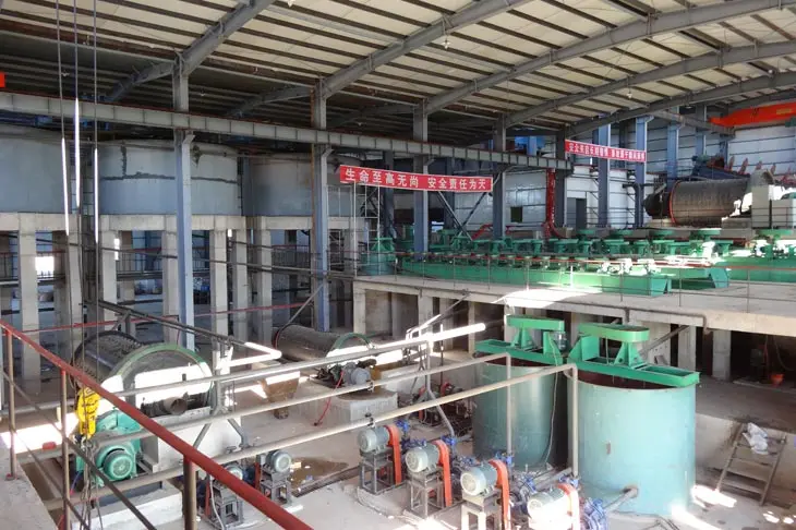
XJ type mechanical agitating flotation machine can be widely used in ferrous metal minerals such as iron, rough selection, selection, sweeping and reverse flotation of non-ferrous metals and non-metallic minerals such as copper, lead, zinc, antimony, molybdenum and gold. However, it is not suitable for rough selection and sweeping operations in large flotation plants.
