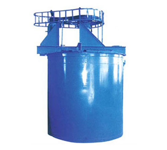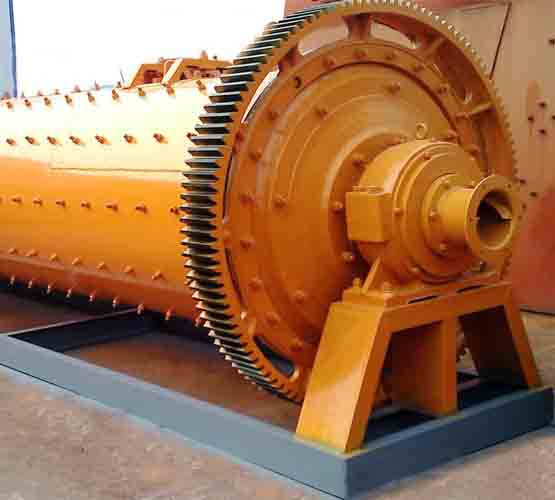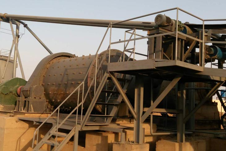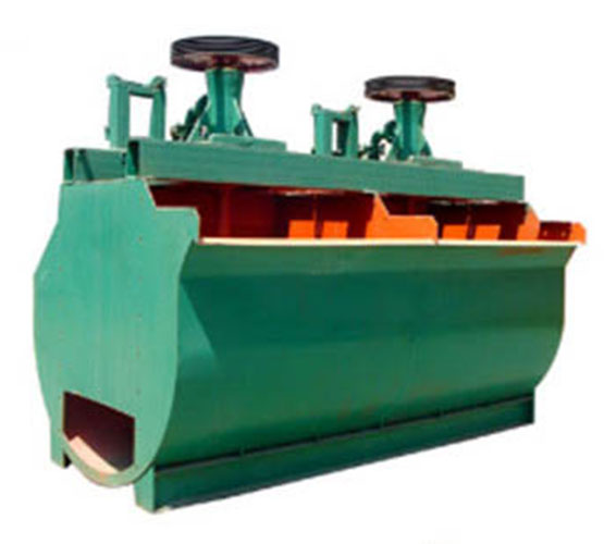
XCF-KYF Integral Unit
The XCF flotation machine is used with the KYF flotation machine. The structural features are similar and the dimensions are the same.
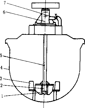
Both XCF and KYF integral unit belong to inflatable flotation machine. With the ability to imbibe ore pulp, SCF is used as ore pulp imbibing tank, while KYF as a direct flow tank without spontaneous imbibition ability. The tanks are arranged horizontally, no foam pump is required.
U-shaped tank reduces the ore accumulated at the bottom of the tank. Large-diameter conical impeller and short blade rotor are adopted, which enable the machine to possess large processing capacity and low energy consumption. Aeration disperser is arranged in the middle of the impeller, which makes the dispersion of aeration uniform and the mixing sufficient.